To write C on the MCU: Writing C on ARM Cortex M0
Example assembly and C code for LPC1114/301: Example Assembly and C Code for ARM Cortex M0 (NXP LPC1114/301)
Example assembly and C code for LPC1114/301: Example Assembly and C Code for ARM Cortex M0 (NXP LPC1114/301)
Step 1. Install Keil MDK ARM v4. Free evaluation version is code size limited to 32k: https://www.keil.com/download/product/
 |
| Figure 1 |
Step 2: Launch “uVision 4” and create a new project.
 |
| Figure 2 |
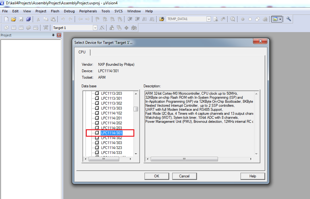
Step 3: Select NXP “LPC1114/301” as the target device.
 |
| Figure 3 |
Step 4. Copy “startup_LPC11xx.s” to the project folder and add it to the current project.
 |
| Figure 4 |
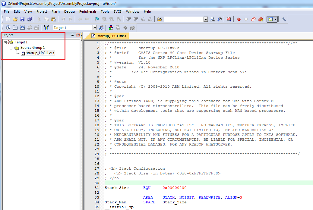
“startup_LPC11xx.s” will appear in the project tree.
 |
| Figure 5 |
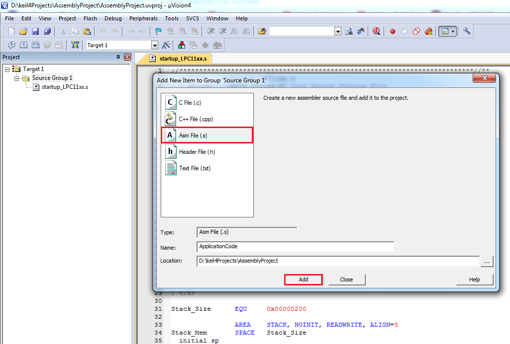
Step 5. Right click on “Source Group 1” in the project tree and add a new assembly source file to the project. This source file will contain the “__main” function and the interrupt service routines.
 |
| Figure 6 |
Select “Asm file” and name it. Then add the .s file to the project.
 |
| Figure 7 |
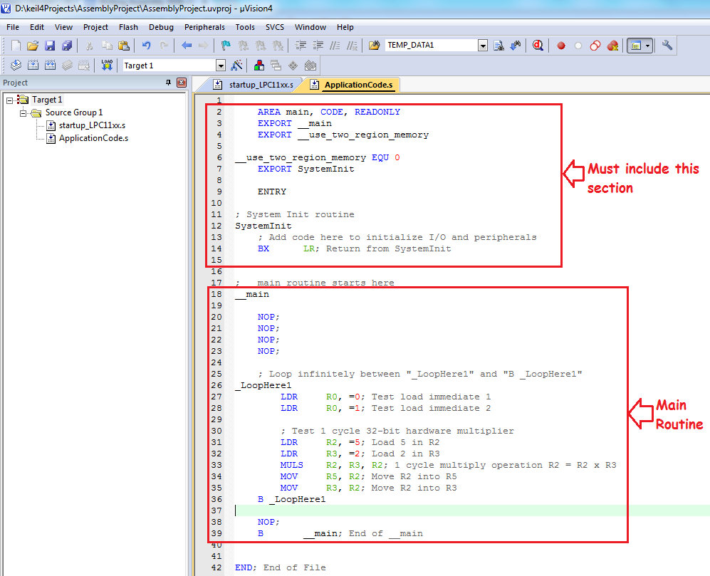
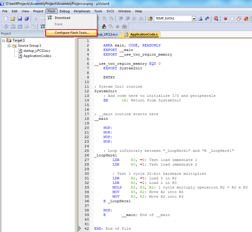
Step 6. Write the assembly code for LPC1114 in “ApplicationCode.s”. Use the template provided in the following figure.
 |
| Figure 8 |
Code for "ApplicationCode.s":
AREA main, CODE, READONLY
EXPORT __main
EXPORT __use_two_region_memory
__use_two_region_memory EQU 0
EXPORT SystemInit
ENTRY
; System Init routine
SystemInit
; Add code here to initialize I/O and peripherals
BX LR; Return from SystemInit
; __main routine starts here
__main
NOP;
NOP;
NOP;
NOP;
; Loop infinitely between "_LoopHere1" and "B _LoopHere1"
_LoopHere1
LDR R0, =0; Test load immediate 1
LDR R0, =1; Test load immediate 2
; Test 1 cycle 32-bit hardware multiplier
LDR R2, =5; Load 5 in R2
LDR R3, =2; Load 2 in R3
MULS R2, R3, R2; 1 cycle multiply operation R2 = R2 x R3
MOV R5, R2; Move R2 into R5
MOV R3, R2; Move R2 into R3
B _LoopHere1
NOP;
B __main; End of __main
END; End of File
|
Another example is provided here in which interrupt service routine is used to toggle one of the MCU pins once every 4.8 million clock cycles.
Step 7. To compile the source code, right click on “Target1” or “Source Group 1” and select “Rebuild all target files”
 |
| Figure 9 |
 |
| Figure 10 |
Few warnings may appear. Ignore them for now.
Step 8. Simulating the code.
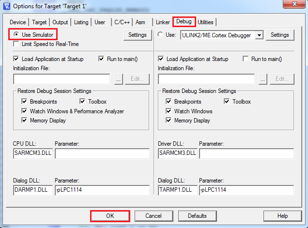
Set “Use Simulator” radio button under the “Debug” tab of “Flash->Configure Flash Tools”. “Options for Target” window will appear. Keep the rest of the settings to the default values.
 |
| Figure 11 |
(Quick: Press “Alt+F7” to bring the “Option for Target” window)
Select “Use Simulator” under the “Debug” tab.
 |
| Figure 12 |
Start the simulation with “Ctrl+F5” or from “Debug->Start/Stop Debug Session”. Evaluation Mode info window will appear. Click “ok” to continue.
Press F11 to single step through the code.
 |
| Figure 14 |
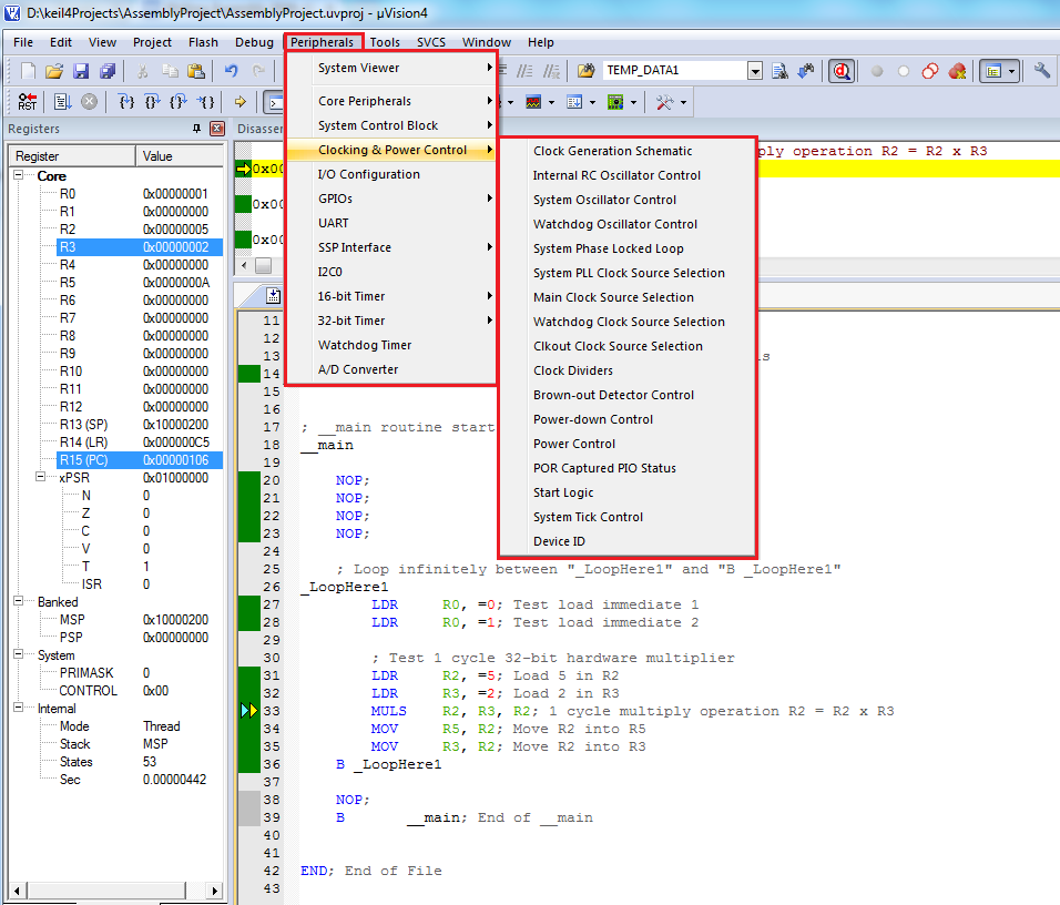
Anytime during the simulation, all the peripheral registers can be observed from the “Peripherals” in the main menu.
 |
| Figure 15 |
Stop the simulation with “Ctrl+F5” or from “Debug->Start/Stop Debug Session”.
Step 9. Generate the .hex file to program the MCU with.
Check “Create .HEX file” box under the “Output” tab of “Flash->Configure Flash Tools”. Then recompile the project. The output .hex file be created in the project directory.
(Quick: Press “Alt+F7” to bring the “Option for Target” window)
 |
| Figure 16 |
Step 10. Program the MCU with the generated .hex file and the LPC21isp tool(http://lpc21isp.sourceforge.net/). A compiled version of the executable “lpcprog.exe” can be downloaded from here.
10a. Connect the development kit to the PC using USB-A to USB-B cable. Download and install the FTDI Vitrual Communication Port Driver, if not installed already.
10b. Make a note of the COM port number at which the the development kit is discovered. Say it is COM7.
10c. To place the MCU into ISP mode, press and hold “RESET + PROG” buttons together on the development kit. Release the “RESET” button FIRST, then release the “PROG” button. The MCU is now in ISP mode.
10d. Open a command prompt and navigate to the place where “lpcprog.exe” is located. Then, type in the following command and press enter.
lpcprog -wipe -verify PATH COM# BaudRate CrystalFrequnecyInKHz
where,
PATH = Absolute path of the .hex file that was generated by Keil
COM# = ‘#’ should be replaced by the serial port number at which the development kit is connected to. If the port number is greater than 9, write “\\.\COMXX” instead of just “COMXX”
Example:
lpcprog -wipe -verify D:\Projects\Project1.hex COM7 115200 12000
|
Here,
PATH = D:\Projects\Project1.hex
COM# = COM7
BaudRate = 115200
CrystalFrequnecyInKHz = 1200010e. Once the MCU is programmed, press “RESET” once to launch the new code.
ARM Cortex M0/M3 development kit
Top surface render of the development kit pcb

Bottom surface render of the development kit pcb

No comments:
Post a Comment